The low fuel warning light started coming on intermittently on my ’96 California 1100 irrespective of the actual fuel level in the tank. I found this distracting while riding, and since I was ignoring it, I ran a real chance of running out of fuel one fine day. Not looking forward to a possible lengthy hike to the nearest gas station, I decided to rectify the situation. Here is a step by step description how I fixed the problem – but please remember, this may not apply to other models.
Looking at the nearly unreadable schematic in the owners manual, it is possible to decipher that the low fuel warning lamp turns on when the tank sensor grounds the lead. Dave Richardson in 'Guzziology' mentioned that on some models the tank can get shorted to the frame and can cause this problem. This may be true for the older models, but for the newer versions the design of the sensor makes it irrelevant whether the tank is grounded to the frame.
The first step is to differentiate two possible causes for intermittent operation: the wire to the warning light shorting to the frame intermittently or a defective sensor. Looking under the left side of the tank, one can see a rubber boot covering the sensor with a black plastic sleeve coming out of it. Gently tugging on this sleeve should bring a white plastic connector into view. The two wires entering the connector are gray and black, and the connector is shaped in cross section like a child’s drawing of a house with a peaked roof. Unplug this connector and check if the low fuel warning lamp is permanently off – if it still turns on intermittently, you have a shorted wire to the lamp which needs to be replaced. Otherwise, the trouble is likely to be the tank sensor itself. One could just buy a replacement sensor, install it and be done. Or, like I did, you can try to repair the sensor, but this is not for the faint of heart.
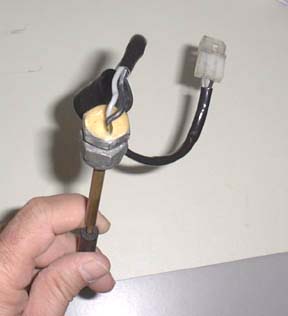
In order to remove the sensor, the fuel has to be drained from the tank. Once the tank is empty, the sensor can be unscrewed from it’s nipple, and carefully withdrawn from the tank. The assembly is a tight fit, so you may have to play with it a little. Photo 1. shows the sensor assembly – if your does not look like it, you are own your own.
The sensor is a switch, but not a simple mechanical one. It is actually a reed switch across the two wires housed in a brass tube. This switch is actuated by a magnet embedded in a small plastic float, which is riding on the brass tube. As long as the fuel level is above minimum, the float is lifted and the reed switch is open. When the fuel level falls below the predetermined level, the magnet in the float is brought into proximity with the reed switch, which now shorts the wires and turns the low fuel level warning light on.
Well, that's the theory. Using a glass enclosed reed switch in a vibration prone environment (if you ride a goose, you know what that is) is probably typical of the optimism displayed by Italian engineers. Realistically, vibration over the years will probably short out the reed switch, preferably intermittently to cause the maximum annoyance - this is what happened to mine.
Getting the defective reed switch out is a royal pain. There are actually two brass tubes protruding from the fitting, a thinner one on which the float is riding, and a thicker one, which simply acts as a stop for the float. If you look at the end of the thinner brass tube, you will see a small cap soldered on – this has to be removed in order to free the float. Carefully unsolder this cap and don’t loose it. Take the float of the tube, but note that one end has a slightly larger hole. This end has to face the larger brass tube when you reassemble the sensor. Also note that there is a thin solid wire protruding (barely) from the end of the brass tube after the cap is removed.
Photo 2. shows the bottom of the sensor assembly. The beige substance filling the cavity of the fitting is a hard plastic into which the wires are potted. You should also note that the gray wire is in the center of the plastic and the black wire is off to one side. The black wire is simply grounded to the fitting, and should be left undisturbed during the rest of this operation. The gray wire is the one connected to the reed switch and has to be freed from the plastic. I trimmed the gray wire flush with the plastic and carefully drilled it out on a drill press using a small bit making sure I did not drill through the brass fitting or the brass tubes. This is tricky, so take it slow. Every so often, grab the thin wire at the end of the brass tube with a pair of pliers and tug – if you have drilled far enough, it should start coming free and you should be able to remove the reed switch assembly. Once you have it out, drill the hole into the plastic larger, but shallow – you will fill this with silicone later.
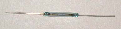
Next you need to find a replacement part. Photo 3. shows what a reed switch looks like, but you can’t just use any old part – there are two specifications that you have to pay attention to : the unit has to be thin enough to slip into the brass tube and sensitive enough to be activated by the puny magnet in the float. I found a suitable one at a local electronics junk shop for 50 cents, but they don’t cost much more than $1-2 new. If you buy new, get the most sensitive available – they are specified in turn-amps, and the lower the number the better.
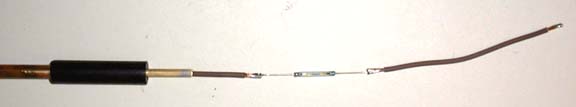
Now take 12” length of automotive wire (thin enough to fit trough the brass tube) and strip about a quarter inch of insulation. Take one end of the reed switch and insert the thin wire coming out of it coaxially into the stripped part of the auto wire and solder it well. You may also have to solder a shorter piece of the same wire to the other terminal of the reed switch to extend it somewhat. Check Photo 4 to see what the finished assembly should look like.
Slip the finished assembly into the thin brass pipe. Slip the float oriented the right way onto the brass thin tube until it rests on the thicker brass tube. Connect a continuity checker or multimeter on the Ohms setting to the two wires. Now carefully move the assembly in and out of the brass tube until you see that the switch has turned on. Mark the wire at the top of the brass tube and pull the assembly back out a little way so that you can strip the wire just below the mark you just made. Push the wire back into its previous position and verify the switch is still on when the float is resting against the larger brass tube. If it all checks out, slip the little cap you removed earlier back on the tube and solder the end of the tube shut.
All you have to do now is to patch the gray wire in the original connector to the wire you used to renew the reed switch assembly with and you are done. Good luck!
Andy “Skipper”
andyal@pacbell.net
